4.4.1/ Reminder
This page content is heavily based on the concepts described before so please read at least the Section 1. In the following we will describe the practical aspects of the implementation.
4.4.2/ Implementation details
Files discussed here are in the dynamic_graph_manager repository. To control a robot using the dynamic graph manager, you need to provide:
- A YAML file
- A class inheriting from the dynamic graph manager
- A main executable that will fetch the YAML file, instantiate you dynamic_graph_manager daughter class and launch everything.
We will discuss in more details the creation of such files in the paragraphs. The sensor and control definitions on the YAML file specify the input and outputs of the robot. Based on this specification, a python Device object is constructed.
4.4.2.1/ The YAML file and the Device.
This YAML file contains the definition of the Device sensors and control signals. In practice this file is supposed to be in the robot_properties_[robot name]/config folder. Please refer to the "create a robot package" section in this wiki for a better understanding. This paragraph assume you read it all.
For the purpose of this demo we decided to not create a specific robot_properties package as this demo is not robot specific. Hence the YAML file is define here: simple_robot.yaml:
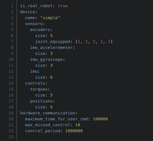
Notice the following nodes:
- "is_real_robot" defines if we are running a simulation or not. If yes the DGM will run a single process.
- "device" is the node that will define the input/output dynamic graph signal and the memory stored in the shared memory.
- this device has a "name" which is used in the infrastructure. Please use something meaningful and the SAME as the one in your URDF file.
- "sensors" contains the list of the sensor name. These names are joined with a "size" node which define the size of the data vector.
- "controls" is the same as the "sensors" but containing the controls name signal.
- "hardware_communication" is the node containing:
- "control_period" in Nano Seconds.
- "max_missed_control" which is the control loop done without update from the dynamic graph. If this "missed control iteration" > "max_missed_control" then the DGM enter in safe control mode (sending 0 torques) which can be overwritten (see below).
- "maximum_time_for_user_cmd" This is the maximum time a hardware asynchronous command MUST take. The hardware communication check if he has the time to execute the command and if possible he does it.
4.4.2.2/ The class inheriting from the DynamicGraphManager
A subclass of the dynamic graph manager, where you initialize the robot hardware, read the sensor values from the hardware into an output map and send the commands to the robot. These maps are strict copies of the YAML files. So in order to add field or remove fields, just modify the YAML file. Example: "simple_dgm.hpp"
In this files there are key method to analyze:
The first is "initialize_hardware_communication_process".
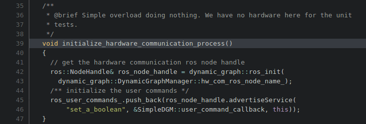
This method is here for you to:
- setup the hardware if needed. Of course this particular class does not have any hardware linked so it does not initialize anything.
- setup the hardware asynchronous command. Typically user defined command on the hardware. Like "what is you IP?" or "Here are gains you must apply!". This mechanism rely on ROS services. Hence one can see here the initialization of the ROS service: "set_a_boolean". Again this class does not have hardware so here is just a simple toy example. Notice the acquisition of the ros::NodeHandle using "ros_init" and the "hw_com_ros_node_name", this will allow your user command to be part of the same namespace as the hardware_communication node.
Next method is "get_sensors_to_map".
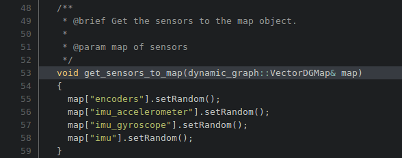
In this method we can notice that:
- the map has already keys assigned to it. These keys are automatically generated using the YAML described above. Notice in the YAML file, the nodes "sensors" which contains the nodes "encoders", "imu_accelerometer", "imu_gyroscope" and "imu". Recognize this names in std::map keys.
- The map is filled using the sensor data. In our case sensor data are pure noise.
- The data from this map are going to be written in the shared memory for the controller to read them.
The third Method is "set_motor_controls_from_map".

In this method we can notice:
- Again we have the map that comes in which has been defined by default from the YAML file. Notice now the nodes under "device" and under "controls". Notice the "torques" and the "positions" nodes in the method and in the YAML file.
- The data read from this map are acquired from the shared memory which in turn is filled by the dynamic graph controller. So one just need to map these controls to the hardware API. In this case, again, we have nothing to do because we have no hardware.
4.4.2.3/ The main file
a main c++ file, which is the entry point for your program: Example: main.cpp

In this one can notice:
- The instantiation of the SimpleDGM class and its trivial use.
- The TEST_CONFIG_PATH is the path to the config folder in https://git-amd.tuebingen.mpg.de/amd-clmc/dynamic_graph_manager/tree/master/tests/config. The YAML we use for this demo is the one used also used for the unit tests. The SimpleDGM is also the class used for the unit tests. So this demo should run without glitches.
4.4.3/ The hardware asynchronous commands:
In this paragraph we are going to explain in details the mechanism behind the user command. First one need to create a ROS service that will perform the asynchronous call. This service is initialized by the user either in the SimpleDGM constructor either in the "initialize_hardware_communication_process" (see paragraph 3.4.2.2/ The class inheriting from the DynamicGraphManager). In order to define a ROS service please refer to http://wiki.ros.org/Services.
This ROS service will use a specific callback method: user_command_callback
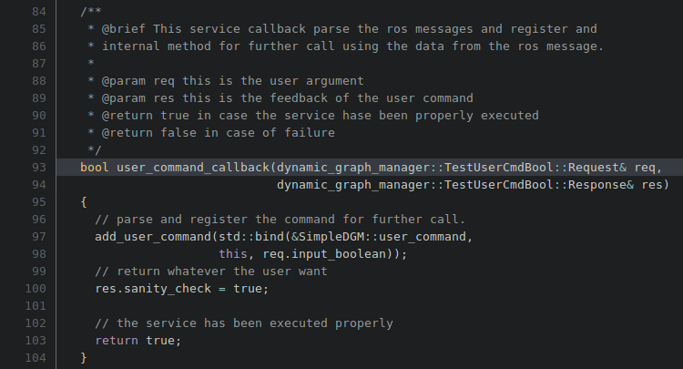
In this code one recognize:
- the ROS declaration of a callback method.
- the results of the service saved in "res.XXXX". Here "res.sanity_check".
- the fact that if everything went fine the method returns "true", which is again a ROS related requirement.
- finally the call to "add_user_command()". It works in the following way:
- This method takes a pointer to a method with the following prototype: "void method(void);".
- In this example we generate this pointer using std::bind. This manages the arguments of the function. In our case this std::bind says that the function to be called "SimpleDGM::user_command" is gonna be called using "req.input_boolean" as argument.
This convoluted behavior is here to ensure safety between real time and non real time behavior. The methods used by ROS are part of the non real time system. Though the hardware user command needs to be executed in the real time thread. This mechanism basically save the user command call into a buffer until the hardware communication process has enough time to execute it.
Please refer to the YAML file once more to notice the node "maximum_time_for_user_cmd" expressed in nano seconds as an integer. In this example we set this time to be 0.1ms. Which means that if the hardware communication thread is sleeping more than 0.1ms then the user command can be executed safely.
Because this system rely on ROS service calls I suggest that the developer of the robot hardware propose a nicer python interface in order to use these commands. See https://git-amd.tuebingen.mpg.de/amd-clmc/dynamic_graph_manager/blob/master/demos/simple_dgm_hwd_client.py
4.4.3/ The safety mode:
As explain in the YAML file description paragraph one can modify when the DGM enter into safe mode and what behavior it should have.
These behavior are also define this demo: is_in_safety_mode and compute_safety_controls:
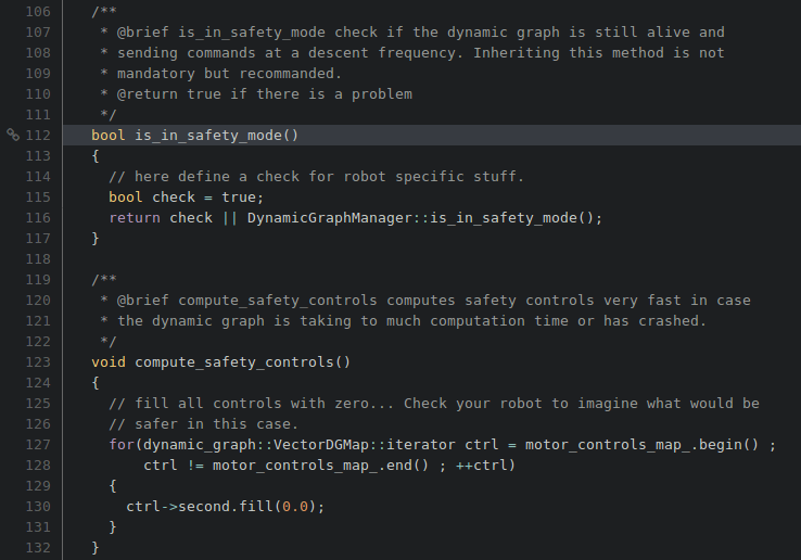
One can identify the inheritance of the detection method as well as the method that computes the safety control.
