| Simplify your CAD files | |
|---|---|
| Original CAD assembly. | 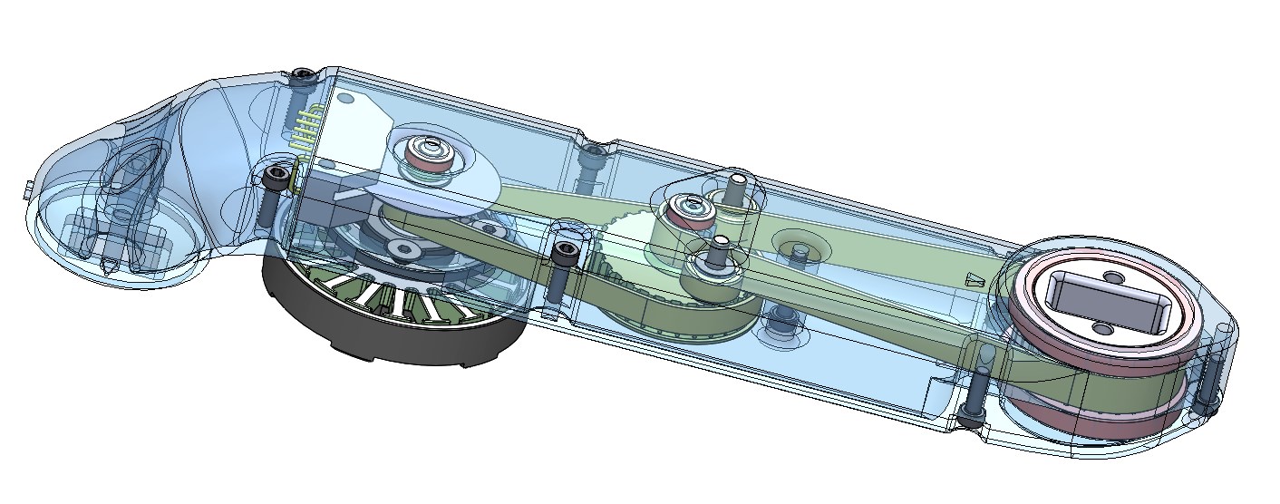
|
| Remove all unecessary component. | 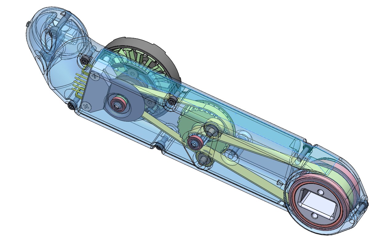
|
| Remove all unnecessary features. | 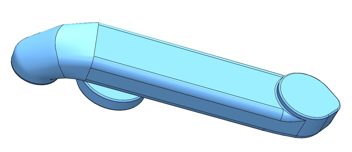
|
| Simplify and remodel sub-assemblies. | 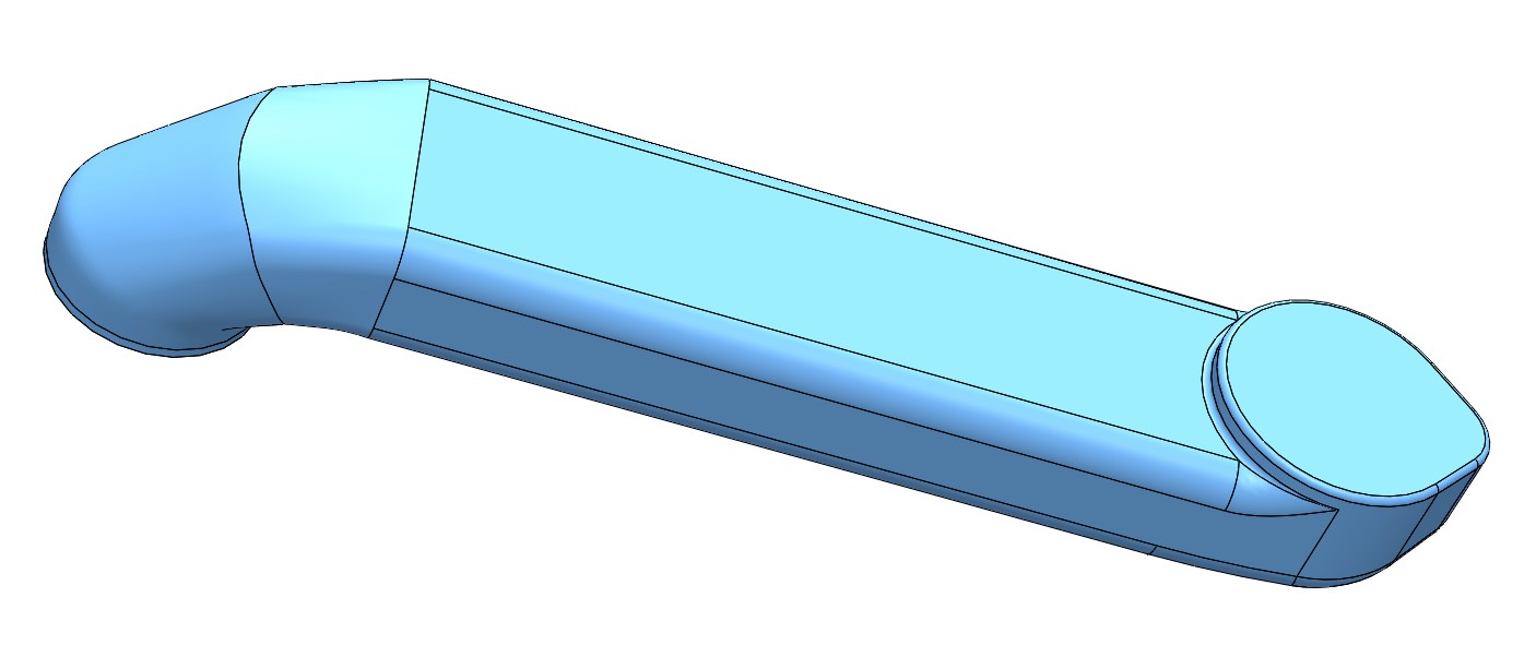
|
| Set your coordinate system to match the conventions | |
|---|---|
Quadruped Coordinate System Convention X→ Forward Y → Left Z → Upwards | 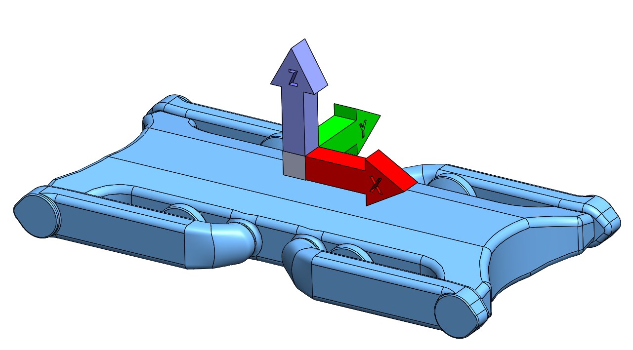
|
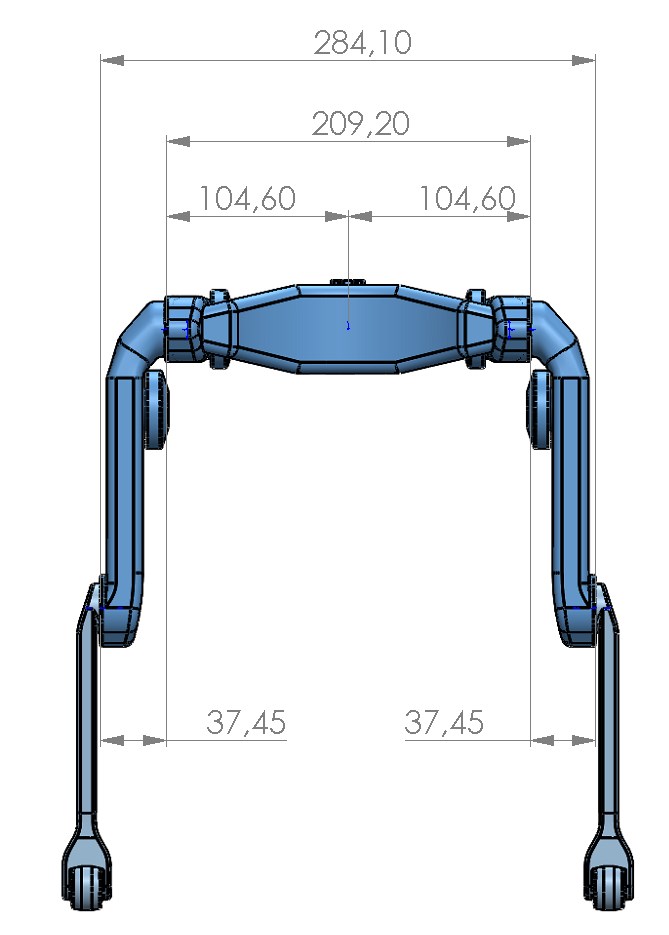
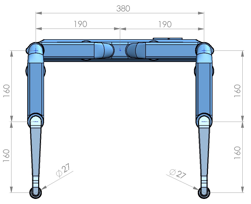
Quadruped Subcomponent Convention In the zero position of the robot all the coordinate systems need to have the same orientation! (see picture on the right) For the quadruped this means that two versions (right side and left side) of the upper leg and the lower leg have to be created. The subcomponent coordinate systems have to be placed on the joint rotation axes and the connecting face. | 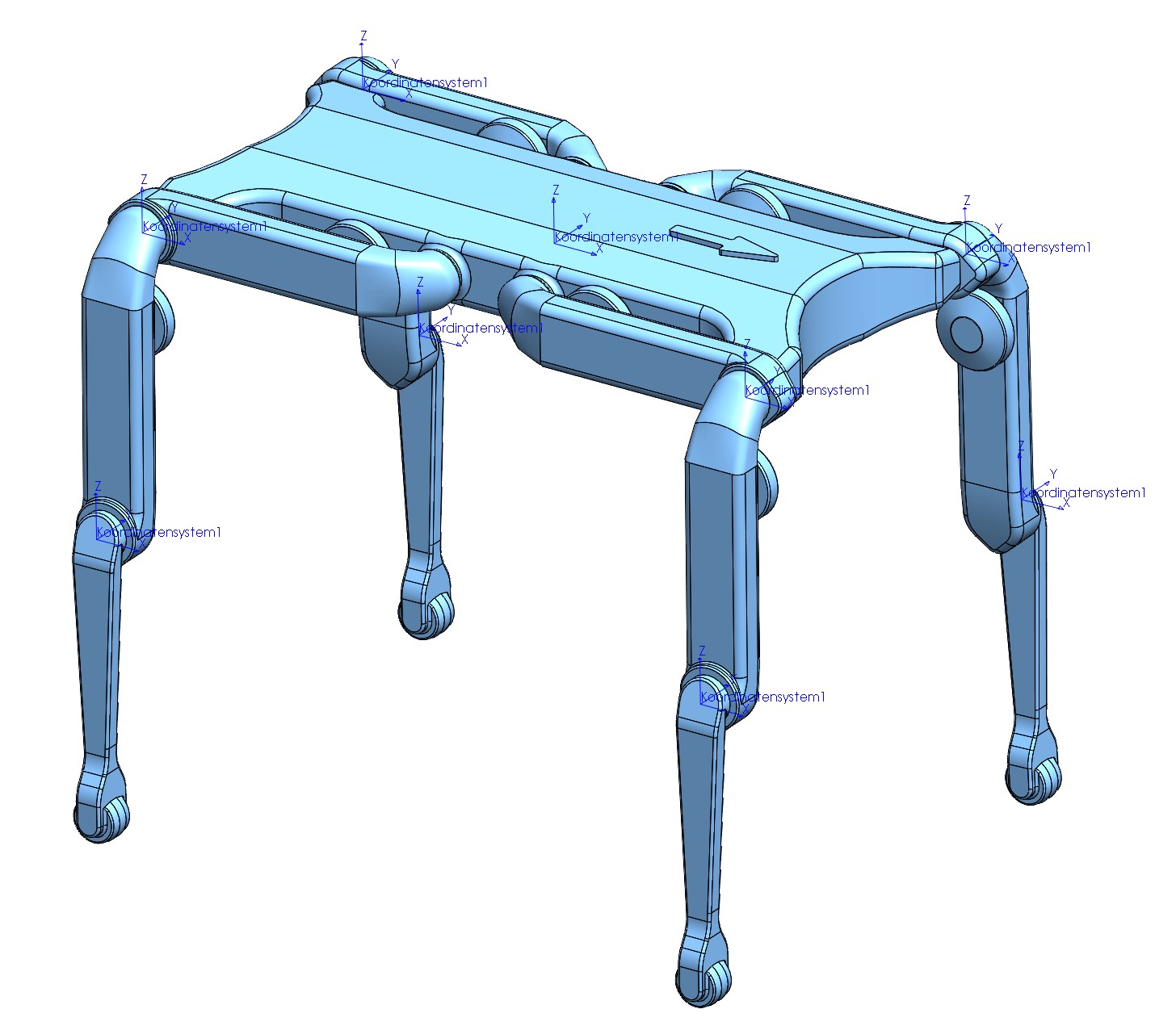
|
If the Solidworks part origin is in the right location you will need to generate 3 axes that intersect at the origin. Got to next step. If the Solidworks part origin is not in the right location you will have to do another intermediate step. Generate an assembly and insert the part. Use the mates funtion to align the part such that the origin of the assembly is in the desired location. Generate three axes that intersect at the origin. Go to next step. Why is this necessary? It seems that Solidworks always places the coordinate systems at the origin. So if the origin is not in the desired location of the coordinate system that has to be corrected first. If there is a better solution to this please update this page. | 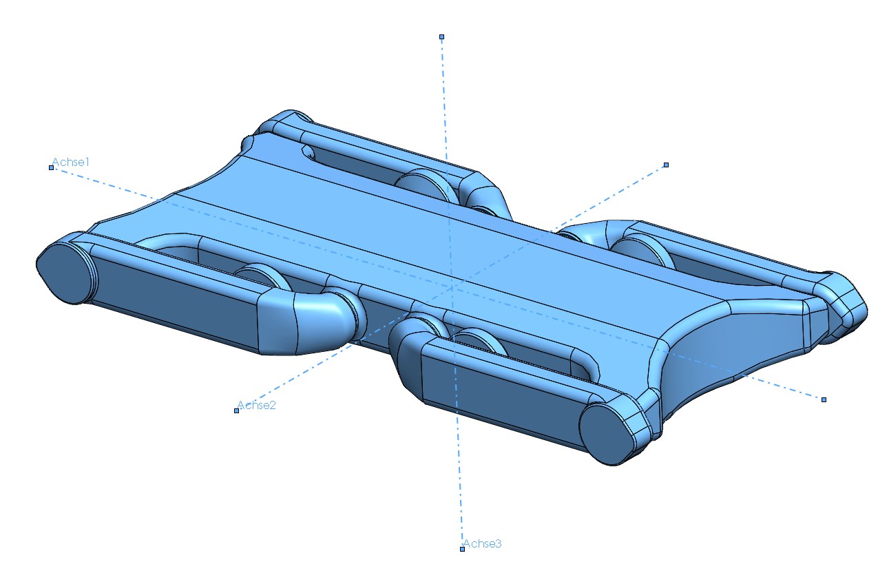
|
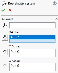
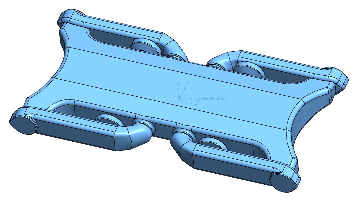
Choose "Reference Geometry". Choose Coordinate System. Select the correct axes and confirm. | 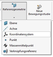
|
| Save as STL file | |
|---|---|
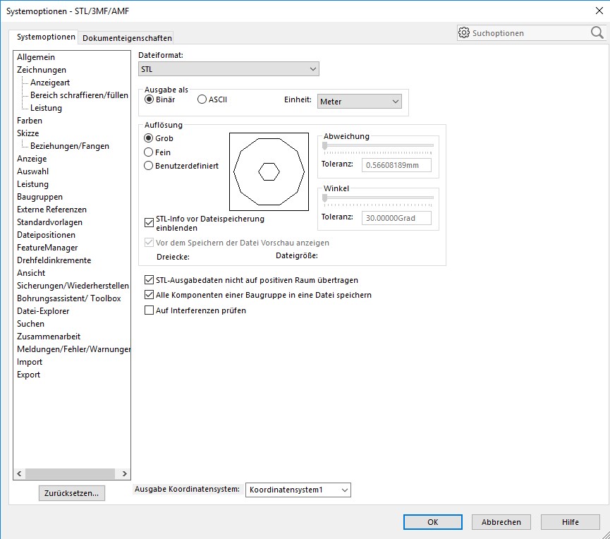
STL File naming conventions:
Example: quadruped_robot_body.stl | |
| 
|
| |
| 
|
